
2 x 500 kVA Electric Hotel Load Converter
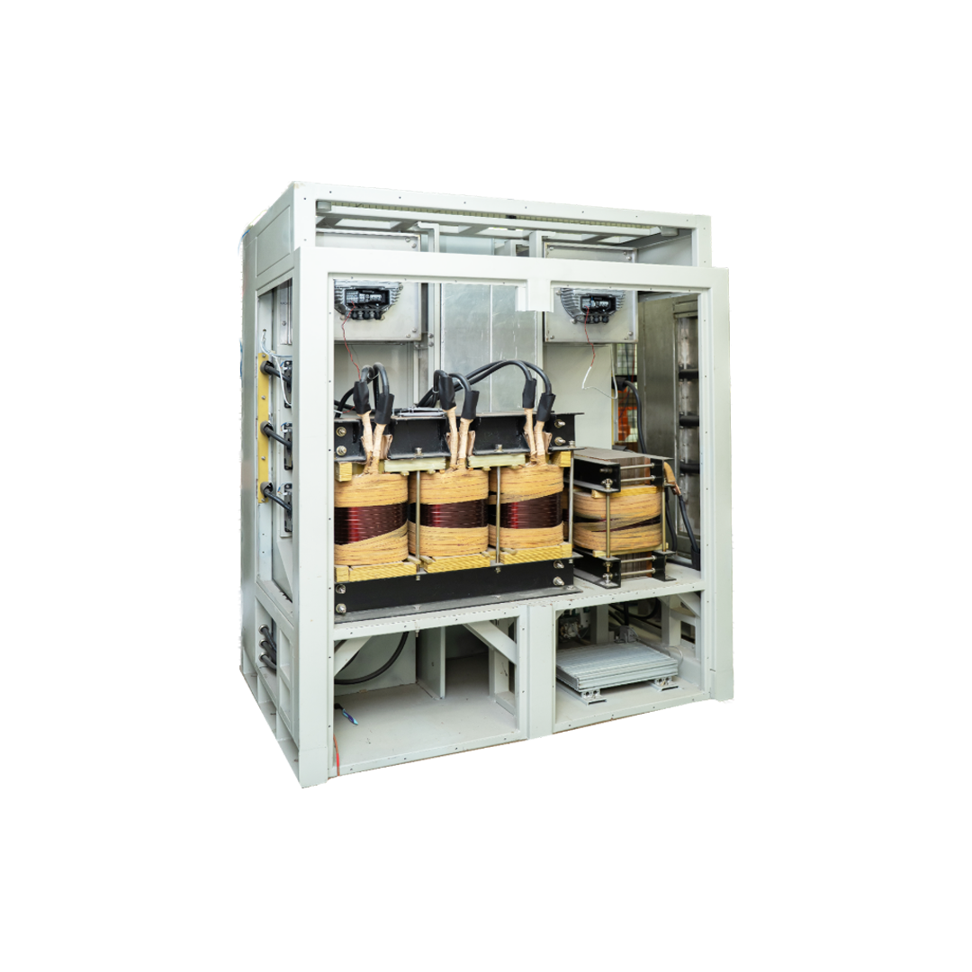
Specification No. CLW/ES/3/IGBT/0490 (Alt.D) Rev-1
What is Hotel Load?
In passenger railway operations, Hotel Load represents the total non-traction electrical power required to maintain
passenger comfort, safety, and onboard catering services. These vital onboard loads include:
- Climate & Environment: Roof Mounted AC Units (RMPUs), heating elements, coach illumination, and air circulation fans.
- Passenger Amenities: Laptop/mobile charging ports, water coolers, and compressed-air water raising apparatus.
- Pantry & Catering Services: Deep freezers, bottle coolers, water boilers, electric hot plates, and cooking appliances.
- Safety & Emergency: Onboard 110 V DC battery chargers for emergency lighting, brake systems, and essential control logic.
Overview & System Concept
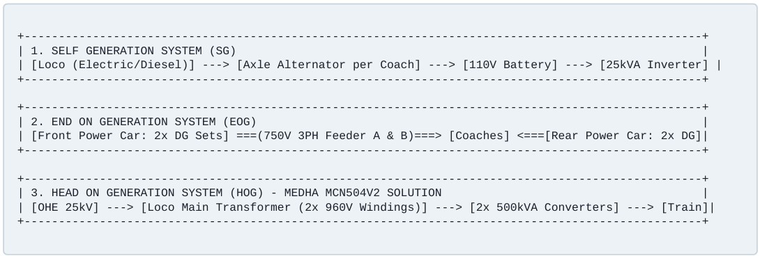
Evolution of Train Power Architecture
Indian Railways employs three distinct technical architectures for feeding electrical hotel load across passenger trains:
- Self Generation (SG): Individual coaches rely on under-slung belt-driven alternators connected to axles. Extremely heavy battery weight, low efficiency, and high maintenance overhead.
- End On Generation (EOG): Dedicated Power Cars at front and rear end with 500 kVA Diesel Generators (DG sets). Incurs high diesel fuel costs, severe noise/smoke pollution, and loss of commercial coach space.
- Head On Generation (HOG – Medha Solution): The locomotive taps power directly from overhead 25 kV AC catenary (OHE) via the pantograph. The main transformer steps down power to two 960 V single-phase hotel load windings. Two Medha MCN504V2 500 kVA Converters synthesize clean, highly stable 750 V 3-phase 50 Hz AC power, eliminating diesel consumption and generator cars.
Technical Specifications & Operating Parameters
The MCN504V2 system is engineered to perform reliably under harsh railway environmental conditions and extreme OHE voltage swings.
| Parameter | Technical Specification & Value |
|---|---|
| Input Supply Voltage (Nominal) | 960 V AC single-phase (from dual 622.5 kVA dedicated transformer hotel load windings at 25 kV nominal OHE) |
| Input Voltage Operating Range | Continuous: 17.5 kV to 30 kV OHE (672 V to 1152 V input); Occasional: 16.5 kV to 31 kV OHE |
| Input Frequency | 50 Hz ± 8% (46 Hz to 54 Hz operating limit) |
| Frequency (f nom) | 50 Hz |
| Input Power Factor & THD | Power Factor > 0.90 (near unity at full load); Input Current THD < 5% up to 20th harmonic |
| Full-Load System Efficiency | > 93% at rated nominal input voltage (960 V AC) |
| Rated Output Power Capacity | 2 × 500 kVA continuous per locomotive (at 0.8 Power Factor) |
| Rated Output Voltage & Waveform | 750 V AC ± 5%, 3-Phase, 3-Wire Sine Wave (50 Hz ± 3%) |
| Voltage Unbalance & THD | Voltage Unbalance < 3%; Total Harmonic Distortion < 10% |
| Direct-On-Line (DOL) Capability | Min. 750 A steady-state motor starting load withstand for 3 seconds |
| Auxiliary Control Power | 110 V DC nominal (75 V to 138 V DC working band) |
| Acoustic Noise & Protection | Acoustic Noise < 80 dB(A) at 1 m distance; IP-54 rated enclosure; Forced Air Cooled |
| Operating Temperature Limits | Internal Loco Temp: -5°C to +55°C (Max +60°C); Under solar soak: up to +75°C |
Converter Architecture & Sub-Assemblies
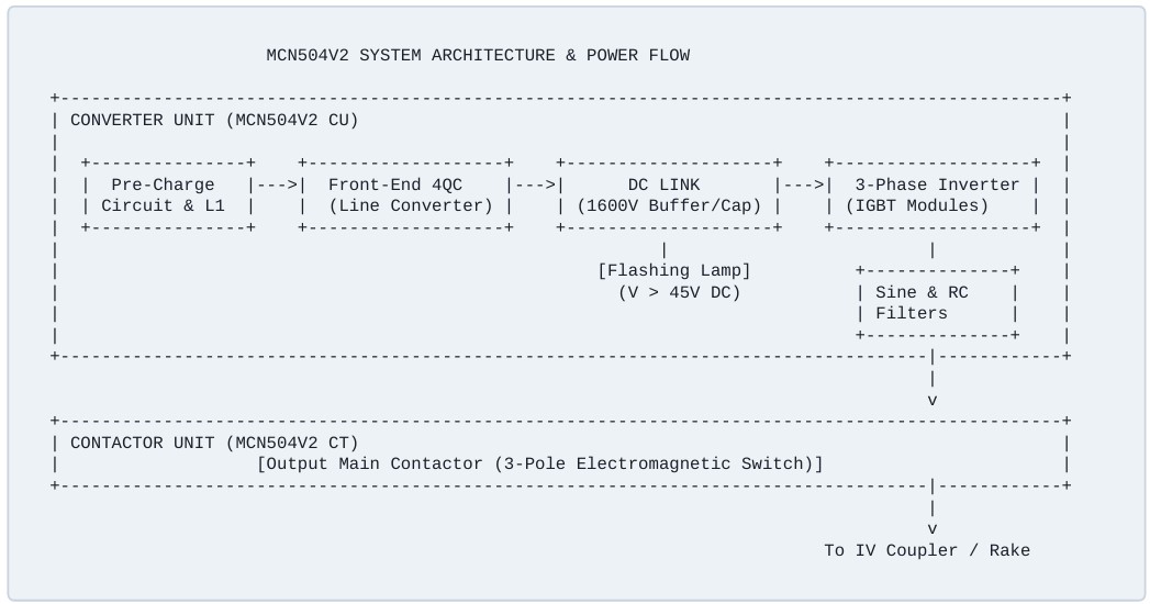
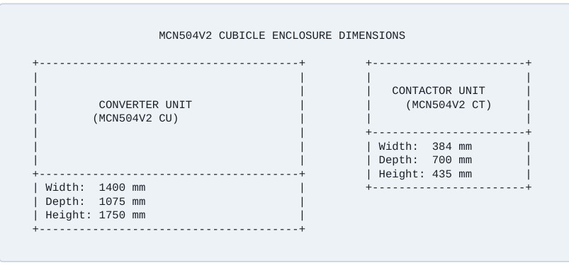
Each 500 kVA system comprises two modular physical enclosures: the main Converter Unit (MCN504V2 CU) and the Contactor Unit (MCN504V2 CT).
Detailed Sub-Assembly Breakdown
- Pre-Charging & Main Input Contactor: Prevents high inrush currents into DC-Link bus capacitors upon power-up by routing initial power through heavy-duty current limiting resistors.
- Four-Quadrant Line Converter (4QC): Active PWM rectifier bridge that converts variable AC input into a stiff, regulated 1600 V DC intermediate voltage link while guaranteeing near-unity input power factor.
- DC-Link Capacitor Bank & Safety Flashing Lamp: Energy storage reservoir providing voltage smoothing and transient suppression. Equipped with an automatic flashing LED warning lamp that flashes whenever residual link voltage exceeds 45 V DC for maintenance safety.
- 3-Phase PWM Inverter & Output Filters: High-frequency IGBT inverter producing 3-phase AC. Integrated LC Sine Filter and Common-Mode RC Earth Filter eliminate PWM carrier ripple, keeping peak phase-to-ground voltage below 800 V.
- Output Contactor Unit (MCN504V2 CT): Heavy-duty 3-pole electromagnetic contactor that isolates the output bus during startup or safety fault conditions.
Control Electronics & Card Rack Architecture
System intelligence is managed by a high-reliability microcomputer rack combining 32-bit DSP speed with 16-bit safety microcontroller redundancy.
| Card Type | Designation | Functional Description |
|---|---|---|
| Main Control Card | M504CC (LC / IC) | Dual-core processor engine (32-Bit DSP + 16-Bit MCU). LC card handles 4QC input PWM and pre-charging; IC card handles inverter output synthesis and logging. |
| Digital Input Card | M504DI | Opto-isolated interface converting 110 V DC loco control logic to safe low-voltage digital signals with status diagnostic LEDs |
| Digital Output Card | M504DO | Solid-state drivers switching 110 V DC contactor coils, safety relays, and external fault lamps with short-circuit protection. |
| Analog Input Card | M504V2 AIP | High-precision signal conditioning card for hall-effect voltage, current, and temperature sensor monitoring. |
| Fiber-Optic Card | M504OFC | 7-channel noise-immune optical fiber transmitter routing gate pulses directly to IGBT driver cards. |
| Control Power Supply | M504PS | Wide-input SMPS (75 V to 138 V DC) supplying regulated internal ±7 V, +5 V, and ±15 V DC rails. |
| Sensor Power Supply | M504V2 SPS | Isolated dual SMPS providing clean ±24 V DC auxiliary power to current/voltage transducers. |
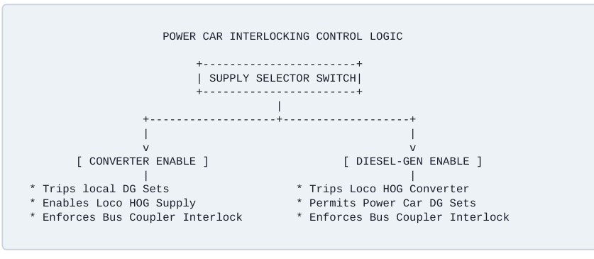
Interlocking & Dual Trainline Interfacing
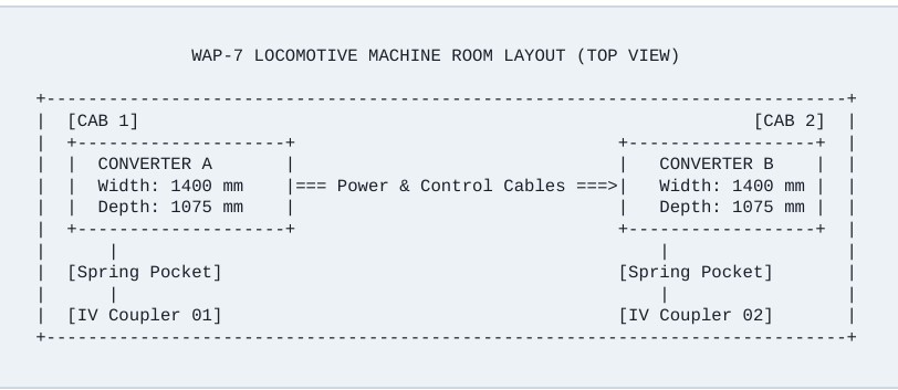
The system connects to trailing power cars via dual 19-core UIC couplers. A dedicated Power Car Interlocking Panel enforces hardware-level electrical interlocking between HOG converter supply and local Diesel Generator sets.
Comprehensive Protection & Diagnostic Suite
The MCN504V2 converter incorporates continuous multi-tiered protection logic to prevent equipment damage under catastrophic grid or trainline faults:
| Protection Subsystem | Monitored Fault Conditions & Thresholds |
|---|---|
| Input / Line Side | Input Under-Voltage (< 495 Vrms for 2 sec) Input Over-Voltage (> 1190 Vrms for 1 sec) Input Over-Current (> 750 A rms / > 1700 A peak) Line Frequency Out-of-Bounds (< 46 Hz or> 54 Hz) Input AC Earth Fault & Open Circuit Detection |
| DC Link & Power Modules | DC Link Instantaneous Over-Voltage (> 1800 V) DC Link Under-Voltage (< 1000 V for 100 msec) 4QC Heat Sink Over-Temperature (> 90°C) Inverter Heat Sink Over-Temperature (> 85°C) IGBT Vce Desaturation & Short-Circuit Protection |
| Output / Load Side | Output Under-Voltage (< 710 Vrms for 5 sec) Output Over-Voltage (> 790 Vrms for 1 sec / > 850 Vrms) Output Earth Fault Current (3 A threshold, 0.5 sec trip) Output Single Phasing (Phase delta > 50 A for 1 sec) Load Short Circuit & DOL Overload Protection |
Mechanical Specifications & Locomotive Layout
EOG-to-HOG Power Car Retrofit Steps
- Feeder Cable Re-routing: Divert vestibule-side power cables to non-vestibule end junction boxes, terminating into
ACB-AandACB-Boutput terminals. - Dummy Sockets Installation: Replace non-vestibule Feeder-B IV sockets with dummy mounting sockets and connect new IV coupler leads directly to power terminals
- Sensing Transformer & Selector Switches: Install mounting brackets holding eight 750 V / 415 V, 100 VA transformers, 32 inline fuse holders, two 6-pole rotary selector switches, and six 400/5 A CTs for door-mounted analog meters.
- Coach Panel Upgrades: Mount Phase Monitoring Relays (
MMR1&MMR2) on glass epoxy insulation sheets (200 × 150 × 4 mm) maintaining a minimum 100 mm creepage gap.