
IGBT Based 3-Phase Propulsion Equipment
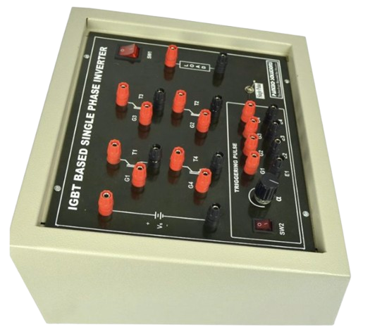
IGBT Based 3-Phase Propulsion Equipment
Specification No. RDSO/2008/EL/SPEC/0071, Rev. ‘5’
Description
- Individual Axle Control: Minimizes the impact of motor failures, ensuring the locomotive continues to operate with only 1/6th power reduction if a single drive-side converter or motor fails.
- High Efficiency & Near-Unity Power Factor: Engineered to deliver maximum power with minimal harmonic distortion, maintaining a power factor close to unity across the entire operating range.
- Intelligent Adhesion & Slip Control: Real-time wheel slip/skidding supervision maximizes tractive effort in all-weather conditions.
- Exceptional Environmental Tolerance: Built to run efficiently in shade temperatures reaching up to 55°C and inside-loco temperatures of 60°C without pre-cooling requirements.
- Smart Energy Management: Integrated software calculates and records real-time energy consumption and regenerative braking feedback.
Technical Specifications :
| IGBT Traction Converter | |
| Redundancy & Fault Isolation | Implements highly robust line-side and drive-side separation to keep locomotives running in degraded modes rather than risking block section failures. The system architecture guarantees dimensions within 3000 × 1100 × 2087 mm (W x D x H) using rugged grade 304 stainless steel cabinets, matching original equipment slots. |
| Proven Cooling Integration | Adapts perfectly to the existing locomotive radiator circuits using an environmentally safe 30:70 green ethylene-glycol and water mixture. Features a completely sealed enclosure conforming to an IP 54 rating for control electronics and power modules to resist dusty and humid railway environments. |
| IGBT Auxiliary Converter (BUR) System | |
| Tri-Modular Configuration | Houses three fully identical 130 kVA auxiliary converters (BUR1, BUR2, BUR3) to provide continuous, isolated sinusoidal output (415 V ± 5% L-L at 50 Hz). Features advanced soft starting capabilities to enable soft starting of heavy auxiliary loads (cooling fans, oil pumps) utilizing variable voltage variable frequency (VVVF) control. |
| Automatic Re-routing | If one BUR unit fails, control system software automatically triggers contactors to re route and sustain all critical auxiliary loads. Includes a fully integrated, independent battery charger supplying a regulated 110 V DC output at 80 A optimized for standard 199 AH Ni-Cd batteries. |
| Safety and Quality Design Standards | |
| Proven Safety Compliance | Designed under strict compliance with protective insulation standards (EN 50153) and electro-technical rolling stock guidelines (IEC 60077). |
| Extensive EMC/EMI Protection | Segmented grounding, robust shielding, and low electromagnetic emission levels conforming to EN 50121 and EN 50238 standards. |
| Reliability Margin | All core power semiconductors (IGBTs) are selected with a minimum voltage and current safety margin of 25% and a junction temperature safety margin of ≥ 10°C under worst-case thermal loads. |
| Open Architecture Vehicle Control Unit (VCU) | |
| Designed on open-architecture network control compliant with IEC-61375 Train Communication Network (TCN) protocols. Advanced diagnostics and non-volatile memory log comprehensive parameters, pre-trigger/ post-trigger wave-forms, and fault data up to card-level for over 100 days. | |
| Out-of-the-box compatibility with existing pneumatic and electronic brake networks, with future-proof multiplexed RS-485 interfaces. The system drives high-resolution Driver Display Units in both cabs, offering real-time status and context-sensitive troubleshooting instructions to the loco pilot. | |
Leading parameters Of Locomotive:
| Parameter | WAG9 locomotive | WAG9H locomotive | WAP7 locomotive | WAP5 locomotive |
| Axle Load | 20.5 tonnes ± 2% | 22.0 tonnes ± 2% | 20.5 tonnes ± 2% | 19.5 tonnes ± 2% |
| No. of axles | 6 | 6 | 6 | 6 |
| Weight | 123 tonnes ± 1% | 132 tonnes ± 1 % | 123 tonnes ± 1 % | 78 tonnes ± 1 % |
| Max. design speed | 100 kmph | 100 kmph | 140 kmph | 160 kmph |
| Test speed | 110 kmph | 110 kmph | 155 kmph | 180 kmph |
Power Supply System:
| Parameter | Values |
| Nominal supply voltage | 25 kV. 50 Hz, single phase, AC |
| Normal variation in supply voltage | 19 kV to 27.5 kV |
| Occasional maximum voltage | 31 kV |
| Occasional minimum voltage | 16.5 kV |
| Variation in supply frequency | ± 8% (46 to 54 Hz) |
Climatic and Environmental Conditions:
| Parameter | Values |
| Atmospheric temperature | Under Sun : 75°C max. In shade : 55°C max. Temp. inside working locomotive may reach 60°C. Minimum temperature: -5°C |
| Humidity | 100% saturation during rainy season. |
| Reference site conditions | i) Ambient Temp.: 50°C ii) Temp. inside loco: 60°C iii) Humidity: 100% iv) Altitude: 1776 m above mean sea level. |
| Rain fall | Very heavy in certain areas. |
| Atmosphere during hot weather | Extremely dusty and desert terrain in certain areas. The dust concentration in air may reach a high value of 1.6 mg/m3. In many iron ore and coalmine areas, the dust concentration is very high affecting the filter and air ventilations systems. |
| Coastal area | Locomotive and equipment shall be designed to work in coastal areas in humid and salt laden atmosphere with maximum pH value Of 8.5, sulphate of 7 mg per litre, max. concentration Of chlorine 6 mg per litre and maximum conductivity of 130 micro siemens /CM |
| Vibration | High level of vibration and shocks. |
Locomotive Performance Envelope:
| Parameter | WAG9 locomotive | WAG9H locomotive | WAP7 locomotive | WAP5 locomotive |
| Starting tractive effort under dry rail condition | Not less than 460 kN | Not less than 500 kN | Not less than 322.6 kN | Not less than 258 kN |
| Continuous rated TE up to speed | Not more than 50 kmph | Not more than 50 kmph | Not more than 70 kmph | Not more than 50 kmph |
| Max design speed | 100 kmph | 100 kmph | 140 kmph | 160 kmph |
| Continuous rated power at rail | Not less than 4500 kW at all speeds from continuous speed to max. design speed | Not less than 4500 kW at all speeds from continuous speed to max. design speed | Not less than 4500 kW at all speeds from continuous speed to max. design speed | Not less than 4000 kW at all speeds from continuous speed to max. design speed |
| Regenerative brake | Maximum possible without skidding over full speed range but not less than 260 KN for WAG9/WAG9Hloco and Maximum possible without skidding over full speed range but not less than 182 KN for WAP7 loco and Maximum possible without skidding over full speed range but not less than 160 KN for WAP7 loco | |||